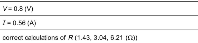
A student investigates circuits containing different combinations of resistors. Circuit A is shown in Fig. 3.1. Circuit A is not complete. Fig. 3.1 The student measures the potential difference $$\(V\)$$ across the parallel combination of resistors $$\(\mathrm{R}_{1}\)$$ and $$\(\mathrm{R}_{2}\)$$ and measures the current $$\(I\)$$ in the circuit. His readings are shown in Fig. 3.2 and Fig. 3.3. (i) Read, and record in the first line of Table 3.1, the values of $$\(V\)$$ and $$\(I\)$$ shown on the meters in Fig. 3.2 and Fig. 3.3. Table 3.1 The student rearranges the resistors between terminals $$\(P\)$$ and $$\(Q\)$$, as shown in Fig. 3.4, to form circuit B and circuit C . The new values of $$\(V\)$$ and $$\(I\)$$ are shown in Table 3.1. Fig. 3.4 (ii) For each circuit, calculate and record in Table 3.1 a resistance $$\(R\)$$. Use the values of $$\(V\)$$ and $$\(I\)$$ in Table 3.1 and the equation: $$\[ R=\frac{V}{I} . \]$$
Exam No:0625_s25_qp_63 Year:2025 Question No:3(b)
Answer:
Knowledge points:
4.2.1.1 State that there are positive and negative charges
Solution:
Download APP for more features
1. Tons of answers.
2. Smarter Al tools enhance your learning journey.
IOS
Download
Download
Android
Download
Download
Google Play
Download
Download